Introduction
Electromagnetic relay is a commonly used component in automatic control. It uses the electromagnetic principle to realize an automatic switch that connects or disconnects one or a group of contacts. It is widely used in electronic equipment, instrumentation, and automation equipment. However, in all kinds of automatic control equipment, there is a problem of interconnection between the low-voltage automatic control circuit and the high-voltage electrical circuit. On the one hand, the control signal of the low-voltage electronic circuit can control the executive elements of the high-voltage electrical circuit; on the other hand, it is necessary to provide good electrical isolation for electronic circuits and electrical circuits to protect the safety of electronic circuits and personnel. For this reason, the PIC16F87X microcontroller is used to control the electromagnetic relay and try to complete this bridging role.
1. Working principle of electromagnetic relay
An electromagnetic relay is a kind of relay that produces a predetermined response by the relative movement of mechanical parts under the action of the current in the input circuit. Electromagnetic relays are generally composed of control coils, iron cores, armatures, contact reeds, etc. The control coils and contact groups are insulated from each other to provide good electrical isolation for the control circuit. It mainly uses the principle of electromagnetic induction to work. When the rated voltage of the coil is added to both ends of the coil of the relay, a certain current will flow in the coil, thereby generating an electromagnetic effect. Under the electromagnetic force, the armature will overcome the pulling force of the return spring and be attracted to the iron core, thereby driving the movable contact and the static contact (normally open contact) of the armature to attract; when the coil is powered off, the electromagnetic suction also disappears, and the armature will return to the original position under the reaction force of the spring so that the moving contact and the original static contact (normally closed contact) are pulled together. The pull-in and release of the relay act as a switch on and off in the circuit. When choosing an electromagnetic relay, the following points should be paid attention to:
(1) Selection of the rated working voltage of the relay. When using a relay, you should first understand the working power supply voltage in the circuit where the relay is located. The working voltage of the relay should be equal to this voltage, or the circuit power supply voltage should be 80% of the working voltage of the relay. The voltage cannot exceed the rated working voltage of the relay, otherwise, the relay coil is easy to burn.
(2) Selection of relay contact load. The number and form of the contact load should be determined according to the characteristics of the circuit controlled by the relay, and then the size of the contact capacity should be selected according to the type of current, voltage, and current in the contact control circuit. The size of the contact capacity reflects the voltage applied to the contact and the ability to pass the current through the contact. Generally, the load of the contact should not exceed the capacity of the contact.
(3) Selection of relay coil power supply. Under normal circumstances, the circuit design uses DC relays, and the type of relays can also be considered according to the characteristics of the control circuit. The power consumed by the relays should also be considered.
(4) Selection of relay action time. The action time and release time of the relay should be selected according to the time requirements of the actual circuit for the action of the controlled object. Additional electronic components can also be added to the relay circuit to accelerate or delay the action and release time of the relay to meet different requirements.
(5) Working environment conditions. When choosing a relay, the temperature of the environment, working life, as well as shock and vibration should also be considered.
2. PIC16F87X control circuit design
2.1 Features of PIC16F87X
The PIC16F87X series 8-bit microcontroller launched by Microchip is a high-performance embedded microcontroller with a reduced instruction set (RISC) structure and Flash storage technology. It runs fast, has rich expansion functions, powerful functions, a clear logic structure, and also has functions such as online programming, power-on, power-down reset protection, and watchdog.
2.2 Principle of the relay control circuit
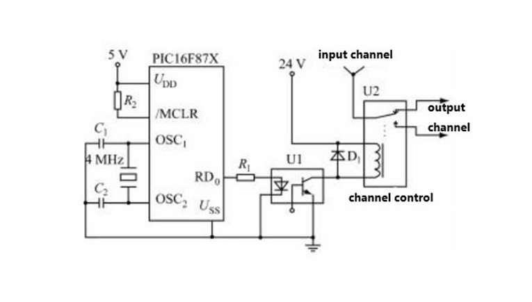
Based on many characteristics of PIC16F87X, the hardware circuit of the PIC16F87X control relay is designed (see Figure 1).

When the RD0 pin of the microcontroller outputs a low level, the optocoupler U1 is turned off, there is no potential difference between the two ends of the relay coil, the relay armature is released, and the normally open contact of the relay is released, which is equivalent to the switch off; when the RD0 pin of the microcontroller outputs a high voltage, the optocoupler U1 is saturated and turned on, the 24V power supply is applied to both ends of the relay coil, the relay is pulled in, and its normally open contact is closed, which is equivalent to closing the switch.
At the moment when the optocoupler is turned off, the current in the coil cannot suddenly change to zero, and a higher voltage-induced electromotive force will be generated at both ends of the relay coil. A diode D1 should be installed at both ends of the coil to release the induced electromotive force generated by the coil through D1, protecting the triode from breakdown and eliminating the interference of induced electromotive force to other circuits.
2.3 PIC16F87X control software design
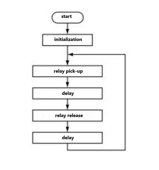
The PIC16F87X control software is developed in C language under MPLABIDE environment and compiled using the PICC compiler developed by Hitech Company. The program flow is shown in Figure 2.

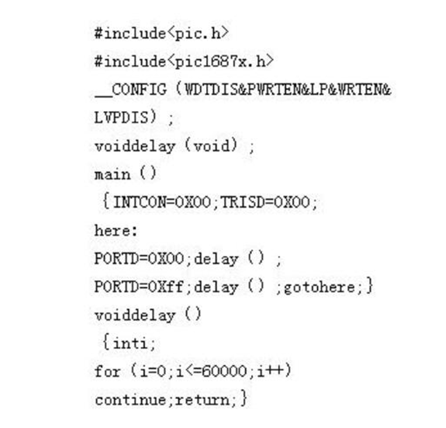
The relay control software source program is as follows:

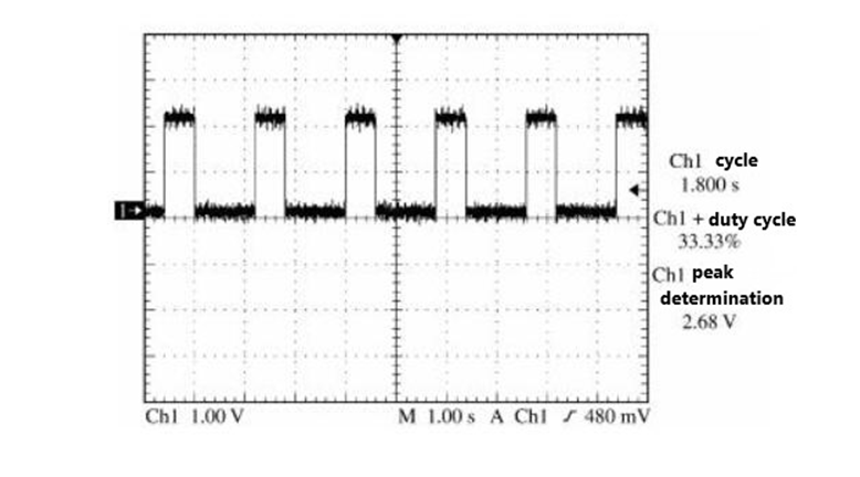
After the source program is compiled, it is programmed into PIC16F87X through ICD2 programming, and the control circuit is powered on to run. Then the relay is repeatedly turned on and off within the specified time. The relay can be heard ringing continuously, and the signal output by the RD0 can be observed with an oscilloscope. It is shown in Figure 3.
3. Conclusion
The electromagnetic relay controlled by the I6X microcontroller adopts an optocoupler to drive and isolate the relay; the diode freewheeling is used to prevent high back pressure when the current in the relay coil is cut off so as to protect the device driving the relay. The circuit is simple in design, reliable in operation, and has a certain application value.


